the Creative Commons Attribution 4.0 License.
the Creative Commons Attribution 4.0 License.
 | 01 Aug 2024
A comprehensive design schedule for electrosprayed thin films with different surface morphologies
Susan W. Karuga
Erik M. Kelder
Michael J. Gatari
Jan C. M. Marijnissen
Electrospraying is a technique in which a liquid jet breaks up into droplets under the influence of electrical forces. The technique is outstanding because of its high deposition efficiency and ability to achieve thin films with different surface morphologies. Nowadays, it is applied in the deposition of thin films for nanoelectronics in lithium-ion (Li-ion) batteries, fuel cells, and solar cells, where the performance of the deposited layers is determined by their morphologies. Although important in the design of thin films, a systematic way of depositing thin films with the desired surface morphologies for optimal operation is not available. In this study, a literature survey has been conducted from which key electrospray parameters have been identified and a comprehensive design schedule for thin films with different surface morphologies has been developed. The developed design schedule specifically targets inorganic salts, as the surface morphology of organic salts, particularly polymers, is subject to diverse factors such as solvent interaction and crystallization behavior. To verify the developed schedule, different thin films have been deposited on aluminum foil substrates using lithium salt precursor solutions by altering key electrospray parameters. Surface morphologies of the thin films have been characterized using scanning electron microscopy. Results show three distinct surface morphologies, porous with agglomerates, porous reticular, and dense particulate morphologies, and they agree with the predictions of the developed design schedule.
- Article
(1616 KB) - Full-text XML
- BibTeX
- EndNote


Electrospraying is a technique in which a liquid jet is broken up into droplets in the presence of electrical forces. This study focuses on electrospraying in the cone-jet mode; therefore, this mode is discussed in depth. The cone-jet mode is usually obtained when a precursor liquid is pumped through a nozzle at a low flow rate such that dripping is observed in the absence of an electric field. However, when an electric field is applied between the nozzle and a counter electrode and the electric field is increased stepwise, other modes can be achieved (as shown in Fig. 1); these include the intermittent cone-jet, spindle (not shown in Fig. 1), cone-jet, and multiple-jet modes (Cloupeau and Prunet-Foch, 1994; Swarbrick et al., 2006). Normally, the cone-jet mode is of interest because of its stability and capability to generate monodisperse droplets that are smaller than the nozzle diameter (Joshi et al., 2021). The precursor solution is pumped through a nozzle, and an electrical voltage is applied between the nozzle and a grounded electrode (or vice versa). The resulting electric field creates a charge on the meniscus of the liquid on the nozzle. Owing to the electric field and the surface charge, the liquid meniscus experiences an electric stress. This electric stress can overcome the surface tension and shape the meniscus into a cone, referred to as the Taylor cone (Taylor, 1964). Charge carriers in the liquid are accelerated towards the cone's apex. They collide with the surrounding liquid molecules, causing them to also accelerate. Consequently, a thin liquid jet emerges from the cone's apex that breaks up into highly charged droplets.
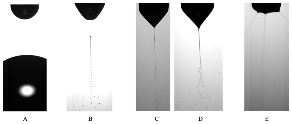
Figure 1Examples of electrospray modes: (a) dripping mode; (b) intermittent cone-jet mode; (c) cone-jet mode, varicose breakup mode; (d) cone-jet mode, whipping breakup mode; and (e) multiple-jet mode. Images reproduced with permission from Verdoold et al. (2014) and Yurteri et al. (2010).
Essentially, when depositing thin films by electrospraying, charged droplets are produced from a precursor liquid and are directed at a substrate of choice. The charged droplets repel one another due to the Coulomb repulsive force between them. This results in self-dispersion on the substrate; the solvent is then evaporated from the droplet's surface, leaving particles to form a solid film. Considering that factors such as the deposited particle sizes, their monodispersity, and their distribution on a surface define the quality of the deposited thin film, electrospraying is a powerful deposition technique. This is because it facilitates the production of uniform films with monodisperse particles in a controlled manner. In their work, Abbas et al. (2017) evaluated the effect of an applied electric field between a nozzle and a ring during spray deposition of Co3O4 thin films, and they referred to this process as electrostatic spray pyrolysis. From their findings, the film produced without an electric field showed defects on the surface, like pin holes, cracks, and crystal flakes, while the film deposited in the presence of an electric field had a smoother, more uniform appearance with uniform crystallinity. In another study by Bansal et al. (2012), an electric field was applied on the substrate, and an ultrathin SnO2 film was deposited using the spray pyrolysis technique. The film showed higher stoichiometry, better crystallinity, a larger grain size, and higher transparency compared with a film deposited without an electric field.
Nowadays, electrospraying is involved in nanotechnology and microelectronics, as the performance of the device in such applications is significantly influenced by the film's surface morphology. For instance, in the deposition of cathode and anode materials for thin films of lithium-ion (Li-ion) batteries, porous or hollow surface morphologies are preferred because they alleviate capacity fading during cycling by providing enough room for contraction and expansion. Moreover, they offer more reaction sites and provide improved electron transport. On the contrary, the electrolyte layer is required to be dense so that it can be effective in inhibiting short circuits (Bezza et al., 2019; Pei et al., 2016). Electrospraying has also been considered to be a breakthrough technique for fuel cell technology, as the performance of a fuel cell's catalyst layer depends on its morphology. Compared with standard electrodes prepared by airbrushing, Conde et al. (2021) reported increased fuel cell performance (by ∼ 20 %) for porous layers deposited by electrospraying. Furthermore, owing to the homogeneous distribution of the electrosprayed layer over the substrate, Silva et al. (2021) reported an enhanced maximum power of the fuel cell (by about 10 %).
In the production of solar cells using the spin-coating technique, perovskite materials have made enormous progress, with a power conversion efficiency exceeding 25 %. However, scaling up the production of perovskite solar cells from laboratory-scale devices to large-scale commercial manufacturing is challenging due to their instability. Furthermore, the conventional methods used to fabricate the solar cells lead to excess material wastage and are not compatible with all of the layers. Therefore, a scalable method with a high material utilization rate is required for the successful commercialization of perovskite solar cells. Electrospraying offers several advantages for manufacturing perovskite solar cells, including the ability to deposit all of the layers. In addition, electrospray can deposit uniform and high-quality layers for enhanced performance and stability of perovskite solar cells, making them more commercially viable. Several studies have reported superior photovoltaic performance for electrosprayed perovskite solar cells. For instance, in the deposition of perovskite thin films for a solar cell, Chandrasekhar et al. (2016) reported a large variation between films deposited with electrospray and spray pyrolysis in terms of surface morphology, surface coverage, and performance. In spray pyrolysis, large droplets were generated, leading to slow evaporation of the solvent. Consequently, a film with voids was formed, and the desired compound material could also not be achieved due to incomplete chemical reaction. On the contrary, electrospraying led to the formation of desired compound on the substrate due to complete reaction. It also generated smaller droplets that led to a more uniform and dense film, and an enhanced efficiency was reported for the electrosprayed film due to efficient electron transfer. While comparing spin-coated and electrosprayed perovskite solar cells, Kavadiya et al. (2017) reported enhanced efficiency and stability for the electrosprayed device, and they attributed this to the achieved uniform and smooth morphology. A power conversion efficiency of 15 % for an entirely electrosprayed perovskite solar cell was reported by Jiang et al. (2018). Moreover, recently, Wu et al. (2021) reported a power conversion efficiency of 14.4 % for an electrosprayed solar cell compared with 11.1 % for a solar cell produced by doctor blading. The electrosprayed layers were compact and dense, ensuring high hole transfer and transport.
It is evident that the surface morphology is critical for enhanced performance in thin films. However, there is limited understanding regarding the accurate control of thin-film morphology. This work provides a systematic way of optimizing different parameters to achieve the desired surface morphologies in the design of thin films. Therefore, parameters that are most relevant for controlling thin-film morphology have been identified. Using these parameters, a systematic design schedule for electrosprayed thin films with different surface morphologies has been developed. Different experiments have also been performed to verify the schedule.
1.1 Theory of the electrospray technique
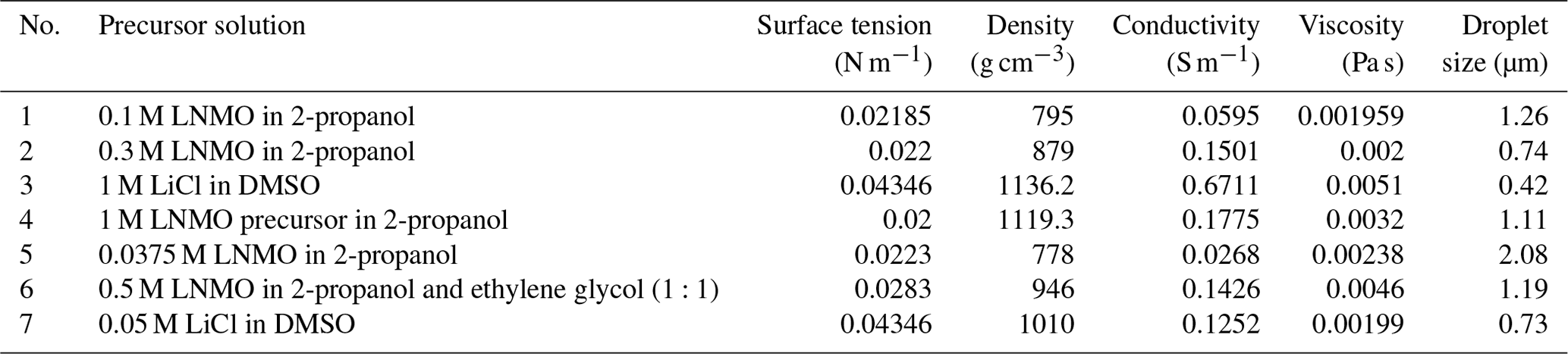
In an electrospray experiment, charged droplets are generated and directed towards a counter electrode, which can be a selected substrate. Upon evaporation of the solvent in the generated droplets, particles are formed. To estimate the sizes of the droplets and particles formed in cone-jet mode, different authors have derived scaling laws. Electric current flowing through the liquid is a key parameter in the estimation of droplet and particle sizes (Yurteri et al., 2010). In the determination of the jet's electric current, Gañán-Calvo et al. (1997) presented two distinct profiles, namely flat and non-flat profiles. According to the aforementioned authors, liquids with high viscosity and high conductivity have a flat, radial profile of the axial liquid velocity in the jet, while liquids with low conductivity and low viscosity have a non-flat velocity profile in the jet. To differentiate between these two categories of liquids, the same authors developed a dimensionless number (Eq. 1), later referred to as the viscosity number (VN) by Hartman (1998).
where γ is surface tension (N m−1), ε0 is electric permittivity of a vacuum (C2 N−1 m−2), μ is liquid absolute viscosity (Pa s), K is liquid conductivity (S m−1), and Q is the liquid flow rate (m3 s−1). For high viscosity and/or high conductivity, the VN is relatively low. In practice, a flat, radial velocity profile is assumed for viscosity numbers less than or equal to 1, while a non-flat, radial velocity profile is assumed for viscosity numbers greater than 1. For a jet with a flat, radial profile, Hartman et al. (1999) derived the equation for electric current as shown in Eq. (2). This scaling law was first introduced by Gañán-Calvo et al. (1993) to show that electric current is a function of liquid properties.
where I∗ is jet current for a flat, radial profile of axial liquid velocity, b=2.17, and the other parameters retain the same meaning as in Eq. (1). For liquids with a non-flat, radial profile, Hartman (1998) derived a formula to calculate the electric current; this formula was rewritten by Yurteri et al. (2010) in the form of Eq. (3).
where I is jet current for a non-flat, radial profile of the axial velocity; I* is jet current for a flat, radial profile of the axial velocity; and Ez,max, , A, and B are all functions of known parameters. The other parameters retain the same meaning as in Eq. (1). Later, Yurteri et al. (2010) combined these formulas in the form of a ratio as a function of VN leading to Eq. (4).
Having calculated the jet's electric current, the mechanism by which droplets are formed during jet breakup is also important and must be considered when determining droplet sizes. This mechanism depends on the ratio of the electric normal stress to the surface tension stress on the liquid's surface. A low stress ratio (< 0.3) results in varicose breakup, while a high stress ratio results in whipping breakup. In the former, main droplets of similar size are obtained; however, satellite or secondary droplets may also form in some cases, resulting in a bimodal size distribution. On the contrary, whipping breakup leads to a broad size distribution of the main droplets (Yurteri et al., 2010). For both mechanisms, Hartman et al. (2000) derived scaling laws for the main droplet size, as shown below.
where dd,varicose is the droplet diameter in the varicose breakup regime, cd is approximately 2, ρ is liquid density (kg m−3), I is the jet's electric current, and the other parameters retain the same meaning as in Eq. (1). Yurteri et al. (2010) demonstrated that if the radial profile of the axial fluid velocity in the jet is flat, the current scales according to Eqs. (2) and (3), leading to Eq. (6).
By approximating the values of b and cd as 2 (as already mentioned above), which gives only a small deviation, Yurteri et al. (2010) obtained Eq. (7).
In the whipping breakup regime, Yurteri et al. (2010) obtained the droplet diameter from Eq. (8).
where dd,whipping is the droplet diameter in the whipping breakup regime, γ is surface tension (N m−1), Q is the liquid flow rate (m3 s−1), and I is the jet's electric current. To calculate the droplet size, both Eqs. (7) and (8) are used, and the smallest value obtained is assumed to be the correct value. It is significant to recognize that Gañán-Calvo (1997) was the first to introduce a general scaling law for estimating droplet size. Their study on the jet breakup showed that it did not affect the surface charge on the jet (Gañán-Calvo et al., 1999). Having determined the size of the main droplets using Eqs. (7) or (8), particle size can be estimated from the main droplet size as shown in Eq. (9) (Yurteri et al., 2010).
where dp is the particle diameter, f is the mass fraction of the dissolved material, ρdroplet is liquid density, ρdroplet is the final particle density, and ddroplet is the droplet diameter. However, this is only true for non-porous and non-hollow particles.
It is important to note that a stable cone jet can only be achieved if electrospray is carried out in a limited voltage and flow rate window. The first quantitative description of this stability window was provided by Cloupeau and Prunet-Foch (1989). For selected liquid properties, this window is defined by a minimum flow rate (Qmin) and a maximum flow rate (Qmax). The former is the lowest flow rate at which a certain liquid can be sprayed in the cone-jet mode (Hartman, 1998), while the latter is the flow rate beyond which the cone jet becomes unsteady. Due to the wide variety of complex issues around the maximum flow rate, there is no formula available to define it (Gañán-Calvo et al., 2018). However, several authors have developed formulas for calculating the minimum flow rate. Among them are Gañán-Calvo et al. (1997) and Hartman (1998), who suggested that the minimum flow rate is given by Eq. (10).
Alternatively, Scheideler and Chen (2014) identified different Qmin scaling laws for low-viscosity (Eq. 11) and high-viscosity (Eq. 12) liquids.
In these equations, Qmin is the minimum flow rate (m3 s−1), ε is the liquid permittivity, ε0 is the electric permittivity of a vacuum (C2 N−1 m−2), γ is the liquid surface tension (N m−1), K is the liquid electrical conductivity (S m−1), ρ is the liquid density (kg m−3), D is the outer nozzle diameter (m), and μ is the liquid viscosity (Pa s). Note that Eq. (11), which was first introduced by Gañán-Calvo et al. (2013), is quite similar to Eq. (10). Other related studies include Montanero et al. (2011), who pointed out that flow rate is a key parameter in determining jet stability in both low- and high-viscosity regimes. They introduced the dependence of flow rate on nozzle diameter, as indicated in Eq. (12). In their work, Qmin increased with viscosity in the low-viscosity regime and decreased with viscosity in the high-viscosity regime. Moreover, Gañán-Calvo et al. (2013) studied the forces influencing the stability of liquid ejection in the cone-jet mode and developed different scaling laws for Qmin based on viscosity and polarization forces. Recently, Marijnissen et al. (2023) extended the work of Hartman, and the former authors came up with a formula to calculate Qmin if all involved liquid parameters are known.
Although not considered in this work, it might be of interest to study the electrokinetic structure of a steady Taylor cone. This is because the dissociation paths of inorganic salts in organic liquids can be extremely complex, leading to the formation of either weak electrolyte solutions or strong electrolyte solutions; in the former, ion distribution and conductivity are homogeneous, whereas they are non-homogeneous for the latter. Therefore, under the same applied voltage, weak electrolyte solutions have larger electrical forces, leading to a shorter cone (López-Herrera et al., 2023). Moreover, when electrospraying with different voltage polarities, the average conductivity for the positive polarity is usually higher than that of the negative polarity. Nonetheless, these differences are negligible for weak electrolyte solutions but significant for strong electrolyte solutions (López-Herrera et al., 2023). In this study, such differences were not expected because only the negative polarity was applied.
1.2 Key parameters influencing electrosprayed film morphology
From the literature, we deduced that the key parameters for designing thin films with different surface morphologies using electrospraying are temperature, flow rate, concentration, and deposition time. These parameters are described in detail below; however, first, we consider the study by Rietveld et al. (2006), who provides guidance with respect to understanding the different parameters.
According to Rietveld et al. (2006), the morphology of an electrosprayed thin film is determined by the film's growth rate, the droplet's shear rate, and the surface energy interactions between the precursor solution and the substrate. The film's growth rate is defined as the amount of material deposited on the substrate per surface area per second, and it is influenced by substrate temperature, flow rate, and spray geometry. At relatively high growth rates, each deposited droplet spreads on the substrate and encounters other similar droplets before it dries up, leading to coalescence. On the contrary, at relatively low growth rates, each deposited droplet dries up independently without coalescing. The droplet's flow on the substrate defines its shear rate; the shear rate is obtained from the stress on the droplet at deposition and the droplet's viscosity, which is proportional to concentration. Whether a droplet will spread on the substrate and wet it depends on the surface energy between the droplet and the substrate, and it is characterized by the contact angle of the droplet. Moreover, Rietveld et al. (2006) highlighted that commonly used electrospray solutions generate droplets that can spread on the substrate and wet it, but they do not discuss the surface energy in detail. Therefore, the viscosity and surface tension are critical parameters in the determination of the droplet spreading on the substrate. In addition, the droplet charge prior to impact and the liquid and substrate conductivities also play an important role. According to Joshi et al. (2021), if the contact angle between the droplet and the substrate is less than 90°, the droplets spread out and wet the substrate, indicating that the surface energy of the substrate is high. Conversely, if the contact angle between the droplet and the substrate is greater than 90°, the droplets show poor wetting on the substrate and tend to form beads, indicating that the surface energy of the substrate is low. Considering that the substrate type in our study does not change, altering the deposition time is critical for changing the contact angles. For a relatively short deposition time, the droplets are deposited directly onto the surface of the substrate; however, at a relatively long deposition time, the contact angle changes because droplets are deposited on top of a layer formed by preceding droplets. Therefore, our deductions on key electrospray parameters are in agreement with Rietveld et al. (2006) and are discussed in detail below.
Note that electrospraying in this study was performed using spray geometries that were restricted to short nozzle–substrate distances (2 or 3 cm). According to Rietveld et al. (2006) and Joshi et al. (2021), the spray distance only affects the area covered by the film and the film thickness. In addition, the selected precursor solutions produced droplets that had a wetting effect on the substrate, just like in the study by Rietveld et al. (2006). This meant that the contact angles between the droplets and the substrate were less than 90°, as explained by Joshi et al. (2021). Lastly, during droplet evaporation, the droplet sizes decrease but their overall electric charges remain constant. Consequently, the Rayleigh limit can be exceeded, causing droplets to explode into many smaller droplets. However, we assumed that the obtained droplet sizes in this study were not affected by this process, as most droplets were impinged before Rayleigh breakup, as in Rietveld et al. (2006).
1.2.1 Temperature
While keeping other parameters constant, different surface morphologies can be achieved depending on the temperature difference between the substrate and the solvent boiling point. This is because both the solvent boiling point and the substrate temperature play a critical role in droplet drying. For instance, using a 0.1 M yttria-stabilized zirconia (YSZ) precursor solution in a solvent mixture of ethanol and butyl CARBITOL (boiling points of 78 and 231 °C, respectively) at a flow rate of 2.8 mL h−1 for 5 h, Perednis et al. (2005) reported a wet film at a substrate temperature lower than the solvent boiling point (200 °C), a dense film at a substrate temperature of 250 °C (substrate temperature was above solvent boiling point at 19 °C), and a particulate film at a substrate temperature of 300 °C (substrate temperature was above solvent boiling point at 69 °C). A high temperature difference led to the evaporation of a large percentage of the solvent from the droplet surface. Therefore, the droplets were almost dry when they arrived on the substrate, leading to the formation of discrete particles and a rough film. Conversely, at low temperature but above the solvent boiling point, the droplets were wet when they reached the surface of the substrate, leading to spreading and contact with each other and forming a smooth film. In their study on the effect of different solvents on particles, Duong et al. (2013) used six alcohols in the preparation of spherical particles, and they obtained different particle morphologies for the different solvents, ranging from smooth spherical particles to collapsed shell morphology. They attributed the difference in particle morphologies to the fact that, at a particular substrate temperature, different solvents evaporate at different rates, causing the droplet sizes to vary. Larger droplets resulted in collapsed particles because of the increased mechanical instabilities. Nonetheless, their results could not be fitted in the developed schedule, as they did not deposit films but, rather, only analyzed particles. Lafont et al. (2012) also obtained a more porous film with 1-propanol than with ethanol (boiling points of 97 and 78 °C, respectively) after electrospraying 0.1 M LiNi0.5Mn1.5O4 (LNMO) precursors at a flow rate of 1 mL h−1 and a substrate temperature of 350 °C (substrate temperature was above the solvent boiling point with a margin of 253 °C).
1.2.2 Flow rate
It has to be noted that, among other parameters, the flow rate controls the droplet size and, hence, the final particle size. However, the flow rate is not an absolute parameter, as it is influenced by other factors, as shown in Eqs. (10), (11), and (12). Among these factors, conductivity is the most prominent, and its variation can lead to a wide range of droplet sizes. Unfortunately, most of these parameters are not mentioned in the literature cited here. It is also important to note that flow rates that can achieve the cone-jet mode are defined by a minimum and a maximum flow rate, and they form an operational window. For future research, it is recommended that all of the involved precursor liquid parameters should be measured and mentioned, as indicated in Table 2. At a constant conductivity, a low flow rate produces relatively small droplets and, hence, small particles, while a high flow rate produces relatively big droplets that dry up into big particles. From Kavadiya et al. (2017), electrospraying 14 mg mL−1 (0.09 M) CH3NH3PbI3 perovskite precursor in isopropyl alcohol (boiling point of 82.5 °C) at flow rates of 0.03, 0.06, 0.09, 0.12, and 0.15 mL h−1 at room temperature led to droplets of diameters 505.88, 635.9, 726.94, 799.33, and 860.41 nm, respectively, and their reported evaporation times were 17.84, 28.22, 36.90, 44.64, and 51.73 µs, respectively. The measured particle sizes were 75.36, 77.00, 109.23, 116.31, and 113.43 nm, respectively. Therefore, smaller particle sizes were achieved at lower flow rates, and they led to the production of smooth uniform films. However, as the flow rate increased (above 0.06 mL h−1), larger particles were obtained, leading to increased film roughness. According to Hong et al. (2017), an intermediate droplet size is required in order to obtain a uniform, dense film. Although they did not give droplet size limits, they explained that small droplets have a high rate of solvent evaporation, leading to a particulate rough film, while big droplets have a low rate of solvent evaporation, leading to an uneven film with pinholes. In their study, the intermediate droplet size was achieved by electrospraying 30 % wt (2 M) MAPbI3 perovskite liquid precursor in dimethyl sulfoxide (DMSO, boiling point of 189 °C) at a flow rate of 0.05 mL h−1 and a substrate temperature of 65 °C for 2 min. The measured droplet size was 4.5 µm, which is considered large for our case. Different morphological effects based on flow rate were also demonstrated by Ma and Qin (2005) during the electrospray of 0.02 M LiFePO4 precursor solution in a mixed solvent of ethanol, glycol, and butyl CARBITOL (boiling points of 78, 197, and 231 °C, respectively) at a substrate temperature of 120 °C (the temperature was lower than the solvent boiling point). At a flow rate of 0.5 mL h−1, the generated particles were big (> 400 nm) and aggregated to form a porous morphology. On the contrary, at a flow rate of 0.05 mL h−1, the generated particles were small (< 100 nm) and formed a uniform, dense film. Furthermore, Yu et al. (2006) reported a porous film with aggregated particles at a flow rate of 4 mL h−1 using 0.02 M LiCoO2 precursor in a mixed solvent of ethanol and glycol (boiling points of 78 and 197 °C, respectively) deposited for 50 min at a substrate temperature of 350 °C.
Table 1A design schedule showing how to obtain different surface morphologies by altering experimental and liquid parameters.
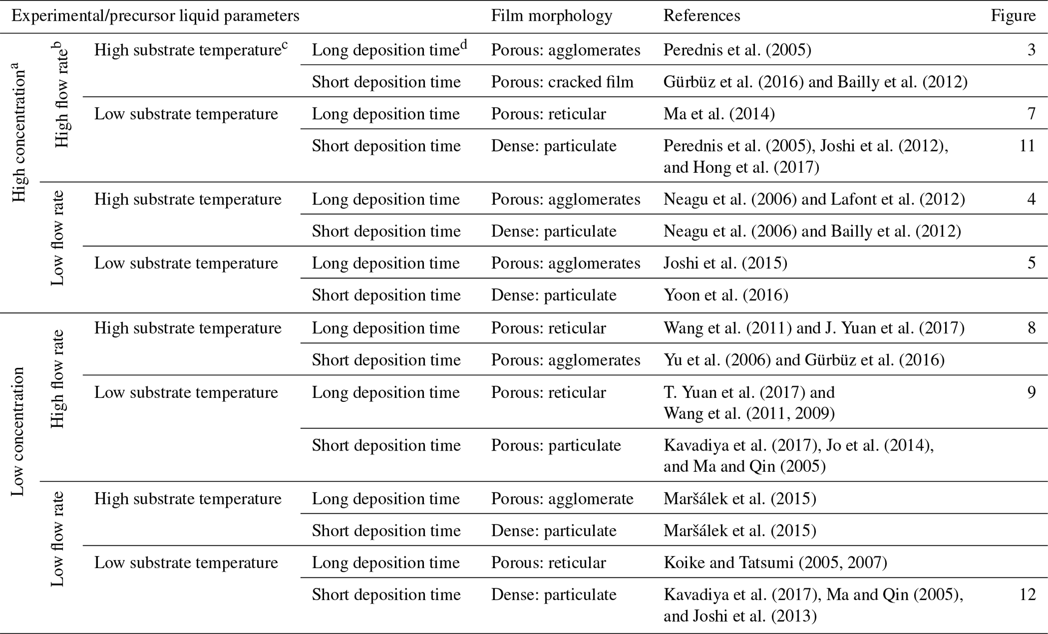
a High concentration is ≥ 0.1 M, whereas low concentration is < 0.1 M. b A high flow rate is characterized by big droplets (≥ 1 µm), whereas a low flow rate is characterized by small droplets (< 1 µm). c A high substrate temperature is a value above the solvent boiling point, with a value of 52 °C or more, whereas a low substrate temperature is a value below the solvent boiling point or above the solvent boiling point, with a value of less than 52 °C. d A long deposition time is > 1 h, whereas a short deposition time is ≤ 1 h.
Table 2Precursor liquid parameters and estimated droplet sizes.
1.2.3 Concentration
Another factor that influences surface morphology is the precursor liquid concentration. According to Gürbüz et al. (2016), an increase in concentration increases the film thickness, thereby affecting the morphology. In their study, they electrosprayed SnO2 precursor in ethanol (boiling point of 78 °C) for 1 h at a substrate temperature of 250 °C. Precursor concentrations were varied from low (0.05 M) to high (0.2 M), but the flow rate was kept constant at 7.2 mL h−1. A crack-free film was obtained from the 0.05 M precursor, whereas a cracked film was obtained after increasing the concentration to 0.2 M. At high concentration, the deposited film was thick, leading to a non-uniform drying rate between the top and bottom layers that caused cracking. Moreover, Bailly et al. (2012) reported a cracked film using a precursor concentration of 0.1 M YSZ in a mixed solvent of ethanol and butyl CARBITOL (boiling points of 78 and 231 °C, respectively) at a flow rate of 0.5 mL h−1 for 1 h and a substrate temperature of 400 °C. In another study, Joshi et al. (2013) reported a dense film from a concentration of 0.05 M (which they considered low) SnCl4.5H2O precursor in propylene glycol (boiling point of 188.2 °C) at a flow rate of 0.04 mL h−1 for 1 h at a substrate temperature of 70 °C.
1.2.4 Deposition time
Deposition time is a very important parameter, not only with respect to determining the layer thickness but also with respect to determining the surface morphology. Over a short deposition time, the film is thin and the droplets come into direct contact with the heated substrate. With increasing time, the film thickens and the substrate surface is completely covered, causing consecutively landing droplets to experience varying contact angles that alter the surface morphology. The effects of deposition time on surface morphology were investigated by Gürbüz et al. (2016), who deposited 0.05 M SnO2 film from an ethanol precursor (boiling point of 78 °C) at a flow rate of 7.2 mL h−1 and at a substrate temperature of 250 °C for various time intervals. After 20 min, they observed that the substrate was sparsely covered because of the small number of deposited droplets. At 60 min, a lot of droplets had been deposited on the substrate, covering the whole surface and leading to a homogenous porous film. After electrospraying a 0.1 M YSZ precursor in a mixed solvent of ethanol and butyl CARBITOL (boiling points of 78 and 231 °C, respectively) at a flow rate of 0.5 mL h−1 and a substrate temperature of 400 °C, Neagu et al. (2006) reported a dense coating at 1 h and rough coatings at 4 and 12 h. They attributed the surface roughness to preferential landing of the droplets which occurred at deposition periods of longer than 1 h. With respect to Maršálek et al. (2015), they prepared manganese oxide layers from a 0.02 M precursor in a mixed solvent of ethanol and water (boiling points of 78 and 100 °C, respectively) at a flow rate of 1 mL h−1 and a substrate temperature of 200 °C. In their case, deposition times of between 10 and 30 min yielded relatively compact and thin layers, whereas longer periods led to a tendency toward agglomeration. In the study by Joshi et al. (2015), they obtained porous films using 0.1 M Bi2WO6 precursor in propylene glycol (boiling point of 188.2 °C) deposited at a flow rate of 0.04 mL h−1 for 80 min and a substrate temperature of 120 °C. They reported increased film porosity with deposition time. In another study, Joshi et al. (2012) obtained a dense film using 0.3 M ZnO precursor solutions in propylene glycol (boiling point of 188.2 °C) at a flow rate of 0.075 mL h−1 for 30 min and a substrate temperature of 200 °C. At deposition times of 10, 20, 40, and 60 min, which they considered to be short, Yoon et al. (2016) obtained uniform compact films from WO3 precursor in mixed solvent of polyethylene and ethanol (boiling points of 200 and 78 °C, respectively) at a flow rate of 0.08 mL h−1 and a substrate temperature of 80 °C. In other studies, a long deposition time led to a porous reticular morphology. As indicated by Koike and Tatsumi (2005, 2007), droplets spread gradually on the substrate surface, and the temperature at the droplet edge was higher than at its center. Therefore, the solvent at the droplet edge evaporated faster than at its center. This process led to ring-shaped nucleation and precipitation that formed a reticular morphology characterized by pores and walls. An example of this is given in Ma et al. (2014), who electrosprayed 0.1 M MnO precursor in 1,2-dihydroxypropane (boiling point of 188.2 °C) at a flow rate of 1.5 mL h−1 for 3 h and a substrate temperature of 240 °C. Another example is given in J. Yuan et al. (2017), who used 2 mM CoMn2O4 precursor in a mixture of ethanol and 1,2-propanediol (boiling points of 78 and 188.2 °C, respectively) a flow rate of 2 mL h−1 for 4 h and a substrate temperature of 250 °C. Furthermore, T. Yuan et al. (2017) used 0.01 M CoMn2O4 precursor in 1,2-propanediol (boiling point of 188.2 °C) a flow rate of 2 mL h−1 for 3 h and at a substrate temperature of 200 °C. The porosity of the film was observed to increase with deposition time, as demonstrated by Wang et al. (2011), who used a 0.03 M V2O5 precursor in a solvent mixture of water, ethanol, and 1,2 propylene glycol (boiling points of 100, 78 and 188.2 °C) at a flow rate of 72 mL h−1 for deposition times ranging from 4 to 12 h and a substrate temperature of 260 °C.
With the aim of enabling the production of thin films with different surface morphologies by electrospraying, a design schedule was developed from the literature, as discussed in Sect. 1.2. However, it was noted that most electrospray studies do not mention all of the parameters, rather only discussing those of interest. For the purpose of this study, only electrospray studies that provided complete information on all of the key parameters were selected and cited. Therefore, for future research, it is recommended that all of the involved parameters should be measured and mentioned. The developed schedule (as shown in Table 1) provides a systematic way of obtaining different surface morphologies by just altering key parameters. The different parameters have been defined in terms of being high or low, and cutoff values have also been derived from cited literature and performed experiments. Consequently, all possible combinations of high (≥ 0.1 M) or low (< 0.1 M) concentration, high (resulting in big droplets ≥ 1 µm) or low (resulting in small droplets < 1 µm) flow rate, high (substrate temperature above the solvent boiling point, 52 °C or more) or low (substrate temperature below the solvent boiling point or above the solvent boiling point, less than 52 °C) temperature, and long (> 1 h) or short (≤ 1 h) deposition time are indicated, providing a systematic way of designing different surface morphologies. Considering that the surface morphology of organic materials, particularly polymers, is influenced by different factors, like their interaction with the solvent and their crystallization behavior (Rietveld et al., 2006b), the developed design schedule is only applicable to inorganic salts.
To verify the developed schedule, different electrospray experiments, the parameters of which are outlined in Table 3, were carried out using the electrospray setup shown in Fig. 2. It consists of a heated substrate holder; a nozzle (EFD Ultra); a high-voltage power supply (FUG HCN14-12500) connected to the nozzle; a syringe pump setup (KD Scientific 100), where a precursor solution contained in a syringe is fed in a controlled flow rate via a chemically resistant hose (Watson-Marlow) to the nozzle; and a temperature controller connected to the substrate holder. The nozzle is held on a movable table, allowing the adjustment of the nozzle–substrate distance. The lithium–nickel–manganese oxide (LiNi0.5Mn1.5O4, LNMO) precursor solutions were prepared by dissolving stoichiometric amounts of reagent-grade lithium nitrate (LiNO3), manganese nitrate (Mn(NO3)2 ⋅ 4H2O), and nickel nitrate (Ni(NO3)2 ⋅ 6H2O) in 2-propanol (boiling point of 82.5 °C). The lithium chloride (LiCl) precursor solutions were prepared by dissolving reagent-grade lithium chloride (LiCl) in dimethyl sulfoxide (DMSO, boiling point of 189 °C). Different precursor solutions were pumped through the syringe at selected flow rates, and the nozzle–substrate distance was 2 or 3 cm. For each experiment, the precursor was sprayed through a metallic nozzle with a 1.54 mm internal diameter. To create an electric field, the substrate holder was grounded while a high voltage of negative polarity was applied on the metallic nozzle. The voltage applied on the nozzle was adjusted for each experiment to yield a steady cone jet. At this point, the liquid meniscus on the nozzle acquired the shape of a cone that did not relax back to a normal droplet shape. After spraying for a selected duration, a thin film was deposited on a heated aluminum foil substrate at a selected temperature to evaporate the solvent. The resulting surface morphologies for the films generated from different experiments were analyzed using a scanning electron microscope (JEOL JSM-6010LA).
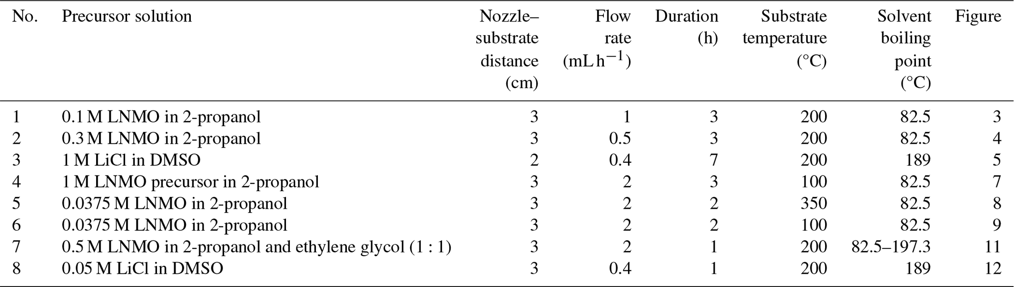
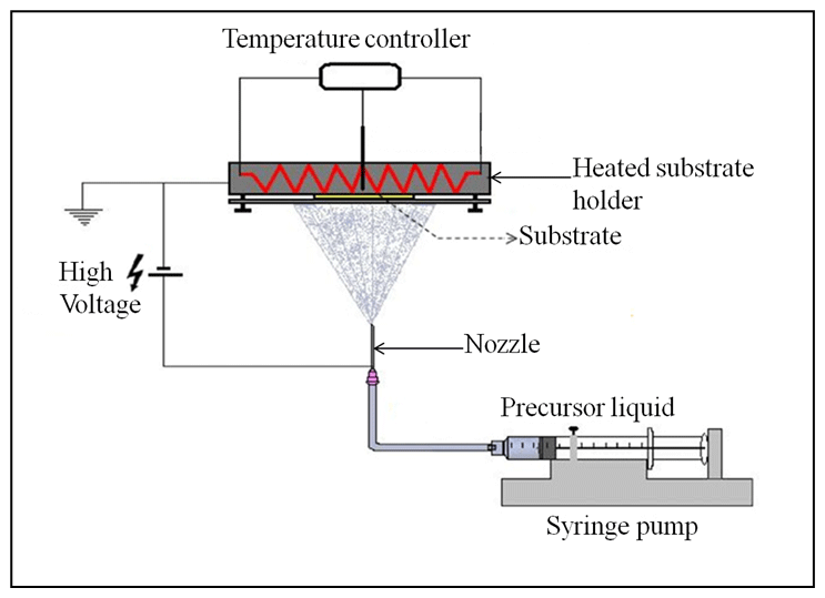
Figure 2Schematics of the electrospray setup used in this study. Reproduced with permission from Li et al. (2011).
As outlined in Table 3, distinct thin films were deposited by altering the identified key parameters. Surface morphologies of the deposited films were then characterized using scanning electron microscopy (SEM). The surface morphologies observed were porous with agglomerates, porous reticular, and dense particulate morphologies. The first morphology observed was porous with agglomerates, as illustrated in Figs. 3 to 5. The thin film in Fig. 3 was obtained from a 0.1 M LNMO precursor solution in 2-propanol (boiling point of 82.5 °C) electrosprayed at a flow rate of 1 mL h−1 for 3 h and a substrate temperature of 200 °C (substrate temperature was above solvent boiling point at 117.5 °C). The surface morphology was in agreement with the prediction of the design schedule (Table 1) after electrospraying a high-concentration precursor solution at a high flow rate on a substrate that was heated at a high temperature for a long spray duration. A similar morphology was reported by Perednis et al. (2005), who electrosprayed a 0.1 M YSZ precursor solution in a solvent mixture of ethanol and 1-methoxy-2-propanol (boiling point of 78 and 120 °C, respectively) at a flow rate of 5.6 mL h−1 for 5 h and a substrate temperature of 260 °C (substrate temperature was above solvent boiling point at 140 °C).
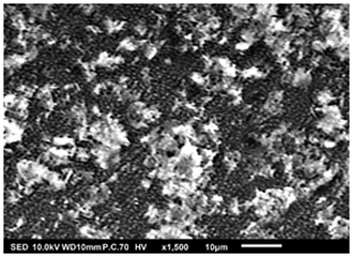
Figure 3SEM image of a thin film generated by electrospraying 0.1 M LNMO precursor in 2-propanol at a flow rate of 1 mL h−1 and a substrate temperature of 200 °C for 3 h.
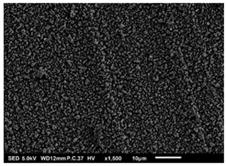
Figure 4SEM image of a thin film generated by electrospraying 0.3 M LNMO precursor in 2-propanol at a flow rate of 0.5 mL h−1 and a substrate temperature of 200 °C for 3 h.
In Fig. 4, another porous film with agglomerates was observed after electrospraying 0.3 M LNMO precursor in 2-propanol (boiling point of 82.5 °C) at a flow rate of 0.5 mL h−1 for 3 h and a substrate temperature of 200 °C (substrate temperature was above solvent boiling point at 117.5 °C). The surface morphology was in agreement with the prediction of the design schedule when a high-concentration precursor solution is electrosprayed at a low flow rate on a substrate heated at a high temperature for long spray duration. Neagu et al. (2006) reported a similar morphology after electrospraying a 0.1 M YSZ precursor solution in a mixed solvent of ethanol and butyl CARBITOL (boiling point of 78 and 231 °C, respectively) at a flow rate of 0.5 mL h−1 at 4 and 12 h spray durations and a substrate temperature of 400 °C (substrate temperature was above solvent boiling point at 169 °C). Moreover, Lafont et al. (2012) obtained a similar morphology after electrospraying 0.1 M LNMO precursor solution in 1-propanol (boiling points of 97 °C) at a flow rate of 1 mL h−1 for 2 h and a substrate temperature of 350 °C (substrate temperature was above solvent boiling point at 253 °C).
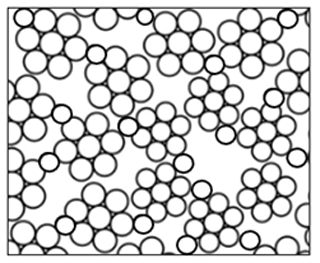
As shown in Fig. 5, a porous film with agglomerates was obtained when a 1 M LiCl precursor solution in DMSO (boiling point of 189 °C) was electrosprayed at a flow rate of 0.4 mL h−1 for 7 h on a substrate that was heated at 200 °C (substrate temperature was above solvent boiling point at 11 °C). The surface morphology was in agreement with the prediction of the design schedule after electrospraying a high-concentration precursor solution at a low flow rate on a substrate that is heated at a low temperature for a long duration. A similar morphology was reported by Joshi et al. (2015) using 0.1 M Bi2WO6 precursor in propylene glycol (boiling point of 188.2 °C) at a flow rate of 0.04 mL h−1 for 80 min and a substrate temperature of 120 °C (substrate temperature was below solvent boiling). They also reported that film porosity increased with deposition time. The porous with agglomerates morphology on the thin films was attributed to the fact that the generated droplets dried in transit, and completely dry particles were deposited on the substrate to form a particulate layer. Subsequently, other particles were deposited on the formed layer, and they experienced resistance during their discharge on the substrate. As a result, preferential landing took place in areas where the particles managed to discharge. The particles then adhered on those positions forming agglomerates that were characterized by aggregates or groups of particles, as illustrated schematically in Fig. 6.
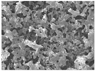
Figure 5SEM image of a thin film generated by electrospraying 1 M LiCl precursor in DMSO (boiling point of 189 °C) at a flow rate of 0.4 mL h−1 and a substrate temperature of 200 °C for 7 h.
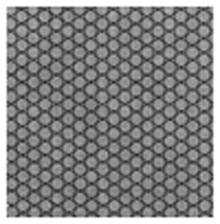
The second type of morphology was the porous reticular morphology, as indicated in Figs. 7 to 9. The thin film in Fig. 7 was obtained when a 1 M LNMO precursor solution in 2-propanol (boiling point of 82.5 °C) was electrosprayed at a flow rate of 2 mL h−1 for 3 h and a substrate temperature of 100 °C (substrate temperature was above solvent boiling point at 17.5 °C). The film's surface morphology was in agreement with the prediction of the design schedule after electrospraying a high-concentration precursor solution at a high flow rate on a substrate that is heated at a low temperature for long spray duration. A similar morphology was reported by Ma et al. (2014), who electrosprayed 0.1 M MnO precursor in 1,2-dihydroxypropane (boiling point of 188.2 °C) at a flow rate of 1.5 mL h−1 for 3 h and a substrate temperature of 240 °C (substrate temperature was above solvent boiling point at 51.8 °C).
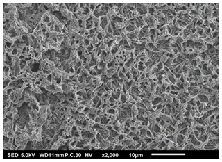
Figure 7SEM image of a thin film generated by electrospraying 1 M LNMO precursor in 2-propanol at a flow rate of 2 mL h−1 and a substrate temperature of 100 °C for 3 h.
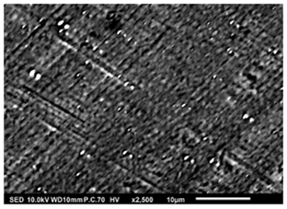
Figure 8SEM image of a thin film generated by electrospraying 0.0375 M LNMO precursor in 2-propanol at a flow rate of 2 mL h−1 and a substrate temperature of 350 °C for 2 h.
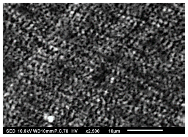
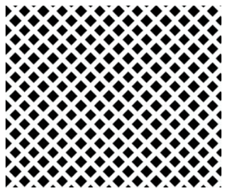
Figure 9SEM image of a thin film generated by electrospraying 0.0375 M LNMO precursor in 2-propanol at a flow rate of 2 mL h−1 and a substrate temperature of 100 °C for 2 h.
Thin films in Figs. 8 and 9 were obtained when 0.0375 M LNMO precursor solution in 2-propanol (boiling point of 82.5 °C) was electrosprayed at a flow rate of 2 mL h−1 for 2 h at a substrate temperature of 350 and 100 °C, respectively (substrate temperature was above solvent boiling point at 267.5 and 17.5 °C, respectively). The films' surface morphologies were in agreement with the predictions of the design schedule after electrospraying a low-concentration precursor solution at a high flow rate on a substrate that is heated at a high temperature (Fig. 7) or a low temperature (Fig. 8) for a long spray duration. T. Yuan et al. (2017) reported a porous reticular film using 0.01 M CoMn2O4 precursor in 1,2-propanediol (boiling point of 188.2 °C) electrosprayed at a flow rate of 2 mL h−1 for 3 h and a substrate temperature of 200 °C (substrate temperature was above solvent boiling point at 11.8 °C). A similar morphology was also reported by Wang et al. (2011), who electrosprayed a 0.03 M V2O5 precursor in a solvent mixture of water, ethanol, and 1,2 propylene glycol (boiling points of 100, 78 and 188.2 °C) at a flow rate of 72 mL h−1 and a substrate temperature of 260 °C (substrate temperature was above solvent boiling point at 71.8 °C). Comparing Figs. 7 and 8, the film became more compact with an increase in substrate temperature. This was also reported by Wang et al. (2009), who obtained porous reticular Fe2O3 films using a 0.005 M precursor in a mixed solvent of 1,2-propylene glycol and ethanol (boiling points of 188.2 and 78 °C, respectively) at a flow rate of 2.4 mL h−1. At substrate temperatures ranging from 170 to 230 °C, they observed a decrease in pore size with increasing substrate temperature. The reticular morphology was characterized by pores and walls just like a mesh, as illustrated schematically in Fig. 10. This was attributed to the uneven drying of droplets, whereby they spread gradually upon arrival on the substrate with a higher temperature at the droplets' edges compared with at their centers. As a result, the solvent at the droplet edges evaporated faster than at the center, leading to ring-shaped nucleation and precipitation and forming a mesh-like morphology.
Lastly, Figs. 11 and 12 show dense particulate surface morphologies. In Fig. 11, the thin film was obtained when a 0.5 M LNMO precursor solution in a solvent mixture of 2-propanol and ethylene glycol (boiling points of 82.5 and 197.3 °C) was electrosprayed at a flow rate of 2 mL h−1 for 1 h at a substrate temperature of 200 °C (substrate temperature was above solvent boiling point at 2.7 °C). The film's surface morphology was in agreement with the prediction of the design schedule after electrospraying a high-concentration precursor solution at a high flow rate on a substrate that is heated to a low temperature for a short duration. Joshi et al. (2012) obtained a similar morphology using 0.3 M ZnO precursor solutions in propylene glycol (boiling point of 188.2 °C) at a flow rate of 75 µL h−1 for 30 min and a substrate temperature of 200 °C (substrate temperature was above solvent boiling point at 11.8 °C). Moreover, Hong et al. (2017), reported a dense film after electrospraying 30 % wt (2 M) MAPbI3 perovskite liquid precursor in DMSO (boiling point of 189 °C) at a flow rate of 0.05 mL h−1 for 2 min and a substrate temperature of 65 °C (substrate temperature was below solvent boiling point). Perednis et al. (2005) also reported a dense particulate film after electrospraying 0.1 M YSZ precursor solution in a solvent mixture of ethanol and butyl CARBITOL (boiling point of 78 and 230 °C, respectively) at a flow rate of 2.8 mL h−1 for 1 h and a substrate temperature of 250 °C (substrate temperature was above solvent boiling point at 20 °C).
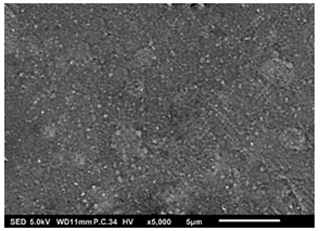
Figure 11SEM image of a thin film generated by electrospraying 0.5 M LNMO precursor in 2-propanol and ethylene glycol at a flow rate of 2 mL h−1 and a substrate temperature of 200 °C for 1 h.
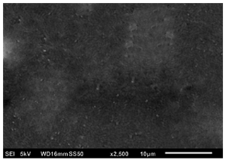
Figure 12SEM image of a thin film generated by electrospraying 0.05 M LiCl precursor in DMSO at a flow rate of 0.4 mL h−1 and a substrate temperature of 200 °C for 1 h.
In Fig. 12, another dense particulate film is shown; it was obtained when a 0.05 M LiCl precursor solution in DMSO (boiling point of 189 °C) was electrosprayed at a flow rate of 0.4 mL h−1 for 1 h on an aluminum foil substrate heated at a temperature of 200 °C (substrate temperature was above solvent boiling point at 11 °C). The film's surface morphology was in agreement with the prediction of the design schedule after electrospraying a low-concentration precursor solution at a low flow rate on a substrate at a low temperature for a short time. Ma and Qin (2005) electrosprayed 0.02 M LiFePO4 precursor solution in a mixed solvent of ethanol, glycol, and butyl CARBITOL (boiling points of 78, 197.3 and 231 °C) at a substrate temperature of 120 °C (substrate temperature was below solvent boiling point). At a flow rate of 0.05 mL h−1, the generated particles were less than 100 nm, and they dried to form a uniform, dense film. Furthermore, Joshi et al. (2013) reported a dense film from a 0.05 M SnCl4.5H2O precursor in propylene glycol (boiling point of 188.2 °C) at a flow rate of 0.04 mL h−1 for 1 h and a substrate temperature of 70 °C (substrate temperature was below solvent boiling point). Similar observations were also made by Kavadiya et al. (2017), who electrosprayed 14 mg mL−1 methylammonium lead iodide perovskite precursor solution (0.09 M) in isopropyl alcohol (boiling point of 82.5 °C) at different flow rates ranging from 0.03 to 0.15 mL h−1 at room temperature (substrate temperature was below solvent boiling). It was evident that the resulting droplet diameters increased with flow rate, ranging from 505.88 to 860.41 nm. The droplet evaporation times also increased with droplet sizes, ranging from 17.84 to 51.73 µs. Upon drying, the resulting particle sizes ranged from 75.36 to 113.43 nm. Thus, smaller particles were achieved at lower flow rates, and they led to the production of dense films characterized by small particles that were in close contact, as illustrated schematically in Fig. 13.
Electrospraying is an efficient technique for the deposition of thin films with diverse surface morphologies, which are crucial for various applications in micro- and nanoelectronics, Li-ion batteries, fuel cells, and solar cells. Our study has highlighted the significance of understanding key electrospray parameters with respect to achieving the desired surface characteristics. Through literature survey, we identified these parameters to be temperature, flow rate, concentration, and deposition time. In addition, we developed a comprehensive design schedule for thin films with different surface morphologies. The applicability of the developed schedule was restricted to inorganic salts, due to the intricate surface morphology and crystallization behavior exhibited by these species. The experimental validation of our design schedule involved depositing thin films on aluminum foil substrates using lithium salt precursor solutions while altering temperature, flow rate, concentration, and deposition time. The spray geometry was restricted to short nozzle–substrate distances, and the selected precursor solutions generated droplets that exhibited a wetting effect on the substrate. Furthermore, it was assumed that droplets were deposited on the substrate before Rayleigh breakup took place. The resulting surface morphologies, as characterized by SEM, revealed three distinct patterns: porous with agglomerates, porous reticular, and dense particulate morphologies. Importantly, these observed morphologies aligned closely with the predictions generated by our design schedule. This research underscores the potential of electrospray deposition as a versatile tool for tailoring thin-film properties to meet specific application requirements. Moving forward, further investigations into optimizing electrospray parameters and their effects on thin-film morphology could lead to enhanced performance and broader applications across various technological domains.
All raw data can be provided by the authors upon request.
SWK and JCMM designed the research; SWK performed the experiments; EMK and SWK analyzed the thin films; SWK wrote the manuscript draft; JCMM, EMK, and MJG reviewed and edited the manuscript; JCMM, EMK, and MJG supervised the work. All authors made substantial contributions to this work.
The contact author has declared that none of the authors has any competing interests.
Publisher’s note: Copernicus Publications remains neutral with regard to jurisdictional claims made in the text, published maps, institutional affiliations, or any other geographical representation in this paper. While Copernicus Publications makes every effort to include appropriate place names, the final responsibility lies with the authors.
We acknowledge the International Science Programme at Uppsala University in Sweden for their financial support. The authors would also like to thank Walter Legerstee for his support during SEM measurements.
This research has been supported by the Centre for Interdisciplinary Mathematics (CIM), Uppsala Universitet (grant no. KEN 01/2, 2017-2021).
This paper was edited by Eirini Goudeli and reviewed by Ivo B. Rietveld and Alfonso Ganan-Calvo.
Abbas, T. A. H., Slewa, L. H., Khizir, H. A., and Kakil, S. A.: Synthesis of cobalt oxide (Co3O4) thin films by electrostatic spray pyrolysis technique (ESP), J. Mater. Sci. Mater. Electron., 28, 1951–1957, https://doi.org/10.1007/s10854-016-5748-y, 2017.
Bailly, N., Georges, S., and Djurado, E.: Elaboration and electrical characterization of electrosprayed YSZ thin films for intermediate temperature-solid oxide fuel cells (IT-SOFC), Solid State Ion., 17, 222–223, https://doi.org/10.1016/j.ssi.2012.06.020, 2012.
Bansal, S., Sharma, S., Pandya, D., and Kashyap, S.: Electric Field Driven Growth of Tin Oxide Thin Films, Energy Procedia, 15, 318–324, https://doi.org/10.1016/j.egypro.2012.02.038, 2012.
Bezza, I., Luais, E., Ghamouss, F., Zaghrioui, M., Tran-Van, F., and Sakai, J.: LiCoO2 with double porous structure obtained by electrospray deposition and its evaluation as an electrode for lithium-ion batteries, J. Alloys Compd., 805, 19–25, https://doi.org/10.1016/j.jallcom.2019.07.062, 2019.
Chandrasekhar, P. S., Kumar, N., Swami, S. K., Dutta, V., and Komarala, V. K.: Fabrication of perovskite films using an electrostatic assisted spray technique: the effect of the electric field on morphology, crystallinity and solar cell performance, Nanoscale, 8, 6792–6800, https://doi.org/10.1039/C5NR08350H, 2016.
Cloupeau, M. and Prunet-Foch, B.: Electrostatic Spraying of Liquids in Cone-Jet Mode, J. Electrost., 22, 135–159, https://doi.org/10.1016/0304-3886(89)90081-8, 1989.
Cloupeau, M. and Prunet-Foch, B.: Electrohydrodynamic spraying functioning modes: a critical review, J. Aerosol Sci., 25, 1021–1036, https://doi.org/10.1016/0021-8502(94)90199-6, 1994.
Conde, J. J., Ferreira-Aparicio, P., and Chaparro, A. M.: Electrospray deposition: a breakthrough technique for proton exchange membrane fuel cell catalyst layer fabrication, ACS Appl. Energy Mater., 4, 7394–7404, https://doi.org/10.1021/acsaem.1c01445, 2021.
Duong, A. D., Sharma, S., Peine, K. J., Gupta, G., Satoskar, A. R., Bachelder, E. M., Wyslouzil, B. E., and Ainslie, K. M.: Electrospray Encapsulation of Toll-Like Receptor Agonist Resiquimod in Polymer Microparticles for the Treatment of Visceral Leishmaniasis, Mol. Pharmaceutics, 10, 1045–1055, https://doi.org/10.1021/mp3005098, 2013.
Gañán-Calvo, A. M., Barrero, A., and Pantano-Rubiño, C.: The electrohydrodynamics of electrified conical menisci, J. Aerosol Sci., 24, S19–S20, https://doi.org/10.1016/0021-8502(93)90102-F, 1993.
Gañán-Calvo, A. M., Davila, J., and Barrero, A.: Current and Droplet Size in the Electrospraying of Liquids, Scaling Laws, J. Aerosol Sci., 28, 249–275, https://doi.org/10.1016/S0021-8502(96)00433-8, 1997.
Gañán-Calvo, A. M.: Cone-jet analytical extension of Taylor's electrostatic solution and the asymptotic universal scaling laws in electrospraying, Phys. Rev. Lett., 79, 217, https://doi.org/10.1103/PhysRevLett.79.217, 1997.
Gañán-Calvo, A. M.: The surface charge in electrospraying: its nature and its universal scaling laws, J. Aerosol Sci., 30, 863–872, https://doi.org/10.1016/S0021-8502(98)00780-0, 1999.
Gañán-Calvo, A. M., Rebollo-Muñoz, N., and Montanero, J. M.: The minimum or natural rate of flow and droplet size ejected by Taylor cone–jets: physical symmetries and scaling laws, New J. Phys., 15, 033035, https://doi.org/10.1088/1367-2630/15/3/033035, 2013.
Gañán-Calvo, A. M., López-Herrera, J. M., Herrada, M. A., Ramos, A., and Montaner, J. M.: Review on the physics electrospray: from electrokinetics to the operating conditions of single and coaxial Taylor cone-jets, and AC electrospray, J. Aerosol Sci., 125, 32–56, https://doi.org/10.1016/j.jaerosci.2018.05.002, 2018.
Gürbüz, M., Günkaya, G., and Doğan. A.: Electrospray deposition of SnO2 films from precursor solution, Surf. Eng., 32, 725–732, https://doi.org/10.1080/02670844.2015.1108048, 2016.
Hartman, R. P. A.: Electrohydrodynamic Atomization in the Cone-Jet Mode. From Physical Modelling to Powder Production. PhD Thesis, Delft University of Technology, ISBN 90-9012086-6, 1998.
Hartman, R. P. A., Brunner, D. J., Camelot, D. M. A., Marijnissen, J. C. M., and Scarlett, B.: Electrohydrodynamic Atomization in the Cone-Jet Mode Physical Modeling of the Liquid Cone and Jet, J. Aerosol Sci., 30, 823–849, https://doi.org/10.1016/S0021-8502(99)00033-6, 1999.
Hartman, R. P. A., Brunner, D. J., Camelot, D. M. A., Marijnissen, J. C. M., and Scarlett, B.: Jet Break-Up in Electrohydrodynamic Atomization in the Cone-Jet Mode, J. Aerosol Sci., 31, 65–95, https://doi.org/10.1016/S0021-8502(99)00034-8, 2000.
Hong, S. C., Lee, G., Ha, K., Yoon, J., Ahn, N., Cho, W., Park, M., and Choi, M.: Precise Morphology Control and Continuous Fabrication of Perovskite Solar Cells Using Droplet-Controllable Electrospray Coating System, ACS Appl. Mater. Interfaces, 9, 7879–7884, https://doi.org/10.1021/acsami.6b15095, 2017.
Jiang, Y., Wu, C., Li, L., Wang, K., Tao, Z., Gao, F., Cheng, W., Cheng, J., Zhao, X. Y., Priya, S., and Deng, W.: All electrospray printed perovskite solar cells, Nano Energy, 53, 440–448, https://doi.org/10.1016/j.nanoen.2018.08.062, 2018.
Jo, Y. J., Kim, Y. H., Jo, Y. H., Seong, J. G., Chang, S. Y., Van Tyne, C. J., and Lee, W. H.: Microporous Ti Implant Compact Coated with Hydroxyapatite Produced by Electro-Discharge-Sintering and Electrostatic-Spray-Deposition, J. Nanosci. Nanotechnol., 14, 8439–8444, https://doi.org/10.1166/jnn.2014.9933, 2014.
Joshi, B., Samuel, E. Kim, Y., Yarin, A. L., Swihart, M. T., and Yoon, S. S.: Electrostatically Sprayed Nanostructured Electrodes for Energy Conversion and Storage Devices, Adv. Funct. Mater., 31, 2008181, https://doi.org/10.1002/adfm.202008181, 2021.
Joshi, B., Yoon, H. Kim, H. Kim, M. Mali, M. G. Al-Deyab, S. S., and Yoon, S. S.: Heterojunction photoanodes for solar water splitting using chemical-bath-deposited In2O3 micro-cubes and electro-sprayed Bi2WO6 textured nanopillars, RSC Adv., 5, 85323–85328, https://doi.org/10.1039/C5RA16833C, 2015.
Joshi, B. N., Yoon, H., and Yoon, S. S.: Structural, optical and electrical properties of tin oxide thin films by electrostatic spray deposition, J. Electrost., 71, 48–52, https://doi.org/10.1016/j.elstat.2012.11.024, 2013.
Joshi, B. N., Yoon, H. Kim, H. Y., Oh, J. H., Seong, T. Y. James, S. C., and Yoon, S. S.: Effect of Zinc Acetate Concentration on Structural, Optical and Electrical Properties of ZnO Thin Films Deposited by Electrostatic Spray on an ITO Substrate, J. Electroch. Soc., 159, H716–H721, https://doi.org/10.1149/2.077208jes, 2012.
Kavadiya, S., Niedzwiedzki, D. M., Huang, S., and Biswas, P.: Electrospray-Assisted Fabrication of Moisture-Resistant and Highly Stable Perovskite Solar Cells at Ambient Conditions, Adv. Energy Mater., 7, 1700210, https://doi.org/10.1002/aenm.201700210, 2017.
Koike, S. and Tatsumi, K.: Preparation and morphology of three-dimensional structured LiMn2O4 films, J. Power Sources, 146, 241–44, https://doi.org/10.1016/j.jpowsour.2005.03.038, 2005.
Koike, S. and Tatsumi, K.: Preparation and performances of highly porous layered LiCoO2 films for lithium batteries, J. Power Sources, 174, 976–980, https://doi.org/10.1016/j.jpowsour.2007.06.219, 2007.
Lafont, U., Anastasopol, A., Garcia-Tamayo, E., and Kelder, E.: Electrostatic spray pyrolysis of LiNi0.5Mn1.5O4 films for 3D Li-ion microbatteries, Thin Solid Films, 520, 3464–3471, https://doi.org/10.1016/j.tsf.2011.12.041, 2012.
Li, X., Dhanabalan, A., and Wang, C.: Enhanced electrochemical performance of porous NiO–Ni nanocomposite anode for lithium ion batteries, J. Power Sources, 196, 9625–9630, https://doi.org/10.1016/j.jpowsour.2011.06.097, 2011.
López-Herrera, J. M., Herrada, M. A., and Gañán-Calvo, A. M.: Electrokinetic modelling of cone-jet electrosprays, J. Fluid Mech., 964, A19, https://doi.org/10.1017/jfm.2023.315, 2023.
Ma, J. and Qin, Q.: Electrochemical performance of nanocrystalline LiMPO4 thin-films prepared by electrostatic spray deposition, J. Power Sources, 148, 66–71, https://doi.org/10.1016/j.jpowsour.2005.01.041, 2005.
Ma, X. H., Wan, Q. Y., Huang, X., Ding, C. X., Jin, Y., Guan, Y. B., and Chen, C. H.: Synthesis of three-dimensionally porous MnO thin films for lithium-ion batteries by improved Electrostatic Spray Deposition technique, Electrochim. Acta, 121, 15–20, https://doi.org/10.1016/j.electacta.2013.12.004, 2014.
Marijnissen, J. C. M., Yurteri, C. U., Karuga, S. W., and Hartman, R. P. A.: On the minimum and maximum flow rate of electrospraying: A practical approach, based on fundamentals, for design purposes, J. Electrostat., 124, 103809, https://doi.org/10.1016/j.elstat.2023.103809, 2023.
Maršálek, J., Chmelar, J. Pocedic?, J., and Kosek, J.: Morphological and electrochemical study of MnxOy nanoparticle layers prepared by electrospraying, Chem. Eng. Sci., 123, 292–299, https://doi.org/10.1016/j.ces.2014.10.044, 2015.
Montanero, J. M., Rebollo-Muñoz, N., Herrada, M. A., and Gañán-Calvo, A. M.: Global stability of the focusing effect of fluid jet flows, Phys. Rev. E, 83, 036309, https://doi.org/10.1103/PhysRevE.83.036309, 2011.
Neagu, R., Djurado, E., Ortega, L., and Pagnier, T.: ZrO2-based thin films synthesized by electrostatic spray deposition: Effect of post-deposition thermal treatments, Solid State Ion., 177, 17–18, 1443–1449, https://doi.org/10.1016/j.ssi.2006.06.024, 2006.
Pei, Z., Li, Z., and Zheng, X.: Porous Materials for Lithium-Ion Batteries, J. Nanosci. Nanotechnol., 16, 9028–9049, https://doi.org/10.1166/jnn.2016.12907, 2016.
Perednis, D., Wilhelm, O., Pratsinis, S. E., and Gauckler, L. J.: Morphology and deposition of thin yttria-stabilized zirconia films using spray pyrolysis, Thin Solid Films, 474, 84–95, https://doi.org/10.1016/j.tsf.2004.08.014, 2005.
Rietveld, I. B., Kobayashi, K., Yamada, H., and Matsushige, K.: Electrospray deposition, model, and experiment: toward general control of film morphology, J. Phys. Chem. B, 110, 23351-23364, https://doi.org/10.1021/jp064147, 2006.
Rietveld, I. B., Kobayashi, K., Yamada, H., and Matsushige, K.: Morphology control of poly (vinylidene fluoride) thin film made with electrospray, J Colloid Interface Sci., 298, 639–651, https://doi.org/10.1016/j.jcis.2005.12.028, 2006b.
Scheideler, W. J. and Chen, C. The minimum flow rate scaling of Taylor cone-jets issued from a nozzle, Appl. Phys Lett., 104, 024103, https://doi.org/10.1063/1.4862263, 2014.
Silva, L. M. G., Leocadio, G. N., de Souza, R. F. B., Mierzwa, J. C., Duong, A., Venancio, E. C., and Neto, A. O.: New approach by electrospray technique to prepare a gas diffusion layer for the proton exchange membrane fuel cell anode, Mater. Today Adv., 12, 100161, https://doi.org/10.1016/j.mtadv.2021.100161, 2021.
Swarbrick, J. C., Taylor, J. B., and O'Shea, J. N.: Electrospray deposition in vacuum, Appl. Surf. Sci., 252, 5622–5626, https://doi.org/10.1016/j.apsusc.2005.12.025, 2006.
Taylor, G. I.: Disintegration of Water Drops in An Electric Field, Proc. R. Soc., A280, 383–397, https://doi.org/10.1098/rspa.1964.0151, 1964.
Verdoold, S., Agostinho, L. L. F., Yurteri, C. U., and Marijnissen, J. C. M. A generic electrospray classification, J. Aerosol Sci., 67, 87–103, https://doi.org/10.1016/j.jaerosci.2013.09.008, 2014.
Wang, S., Li, S., Sun, Y., Feng, X., and Chen, C. Three-dimensional porous V2O5 cathode with ultra high rate capability, Energy Environ. Sci., 4, 2854–2857, https://doi.org/10.1039/c1ee01172c, 2011.
Wang, L., Xu, H. W., Chen, P. C., Zhang, D. W., Ding, C. X., and Chen, C. H.: Electrostatic spray deposition of porous Fe2O3 thin films as anode material with improved electrochemical performance for lithium–ion batteries, J. Power Sources, 193, 846–850, https://doi.org/10.1016/j.jpowsour.2009.03.063, 2009.
Wu, C., Wang, K., Jiang, Y., Yang, D., Hou, Y., Ye, T., Han, C. S., Chi, B., Zhao, L., Wang, S., Deng, W., and Priya, S.: All electrospray printing of carbon-based cost-effective perovskite solar cells, Adv. Funct. Mater., 31, 2006803, https://doi.org/10.1002/adfm.202006803, 2021.
Yoon, H., Mali, M. G., Kim, M., Al-Deyab, S. S., and Yoon, S. S.: Electrostatic spray deposition of transparent tungsten oxide thin-film photoanodes for solar water splitting, Catal. Today, 260, 89–94, https://doi.org/10.1016/j.cattod.2015.03.037, 2016.
Yu, Y., Shui, J. L., Jin, Y., and Chen, C. H.: Electrochemical performance of nano-SiO2 modified LiCoO2 thin films fabricated by electrostatic spray deposition (ESD), Electrochim. Acta, 51, 3292–3296, https://doi.org/10.1016/j.electacta.2005.09.021, 2006.
Yuan, J., Chen, C., Hao, Y., Zhang, X., Agrawal, R., Wang, C., Li, X., Hao, Y., Liu, B., Li, Q., and Xie, Y.: Three-dimensionally porous CoMn2O4 thin films grown on Ni foams for high-performance lithium-ion battery anodes, J. Mater. Sci., 52, 5751–5758, https://doi.org/10.1007/s10853-017-0810-6, 2017.
Yuan, T., Jiang, Y., Wang, Q., Pan, B., and Yan, M.: Pseudocapacitance-Enhanced High-Rate Lithium Storage in “Honeycomb”-like Mn2O3 Anodes, ChemElectroChem, 4, 565–569, https://doi.org/10.1002/celc.201600588, 2017.
Yurteri, C. U., Hartman, R. P. A., and Marijnissen, J. C. M.: Producing Pharmaceutical Particles via Electrospraying with an emphasis on Nano and Nano structured Particles – A Review, KONA Powder Part. J., 28, 91–115, https://doi.org/10.14356/kona.2010010, 2010.